


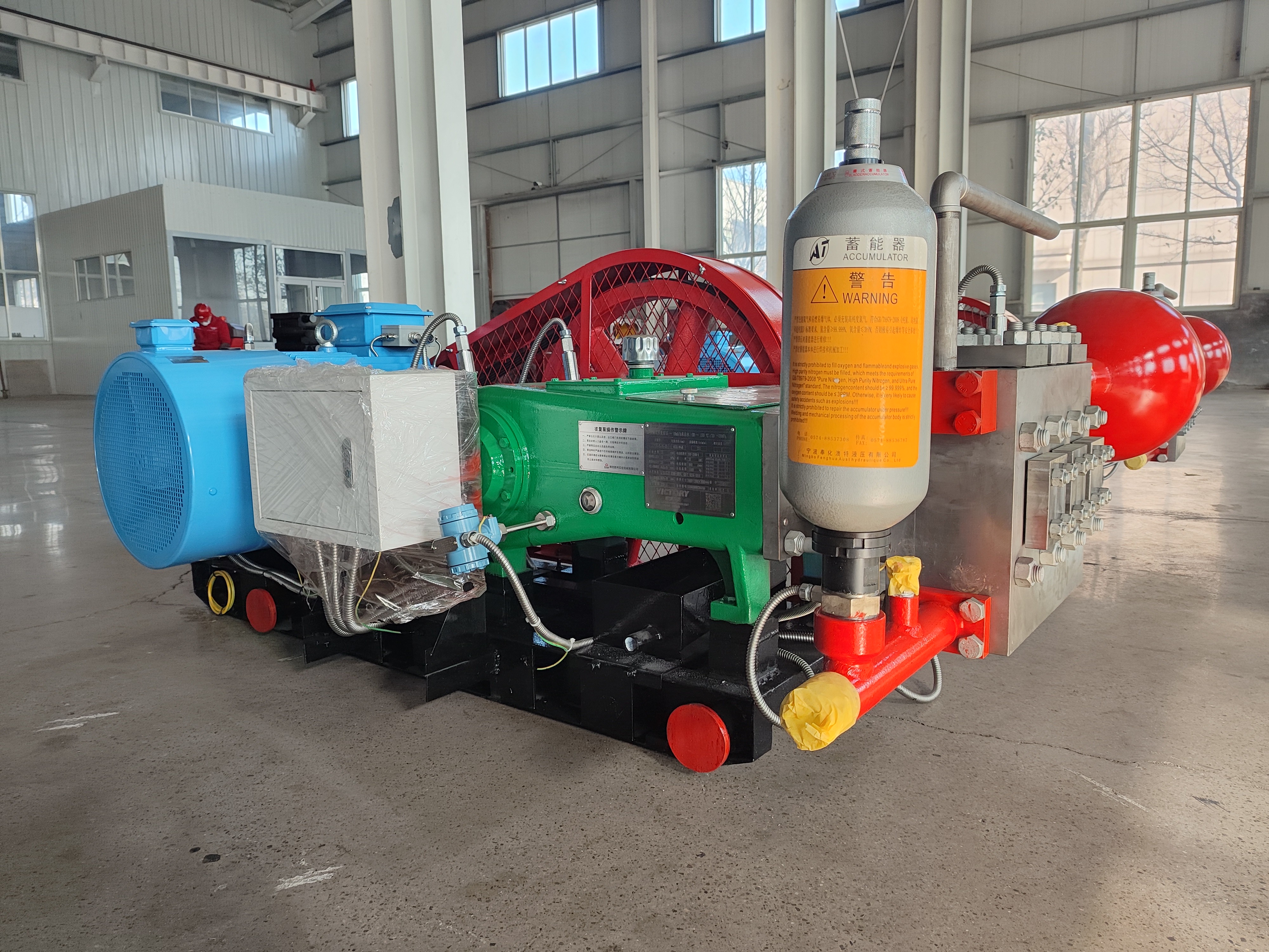
Deck: When part of a mature waterflood misses its injection target, a booster at the wellhead usually beats a bigger pump at the plant.
Mature waterflood fields rarely lose injection capacity everywhere at once. More often, most of the field still takes water at its allocation while a subset of wells — a block, a fault compartment, a tighter sand — falls behind. A recent programme at Sinopec's Binnan production plant in China's Shengli Oilfield is a public and well-documented example: over the first ten months of 2026 the plant raised effective daily water injection by 19,000 cubic metres, and its waterflood reservoirs produced 54,000 more tonnes than in the same period a year earlier*1,*2.
Underneath those numbers sits a question every mature-field operator eventually faces: when part of the field misses its injection target, do you raise the pressure of the whole system, or add pressure only where it is missing? In most mature-field cases, the second option — a booster pump at the wellhead or well pad — is the better answer. This article sets out why, the signals that point to a booster, where it connects, and what to fix in the specification before you buy.
What "booster injection" means in a mature waterflood
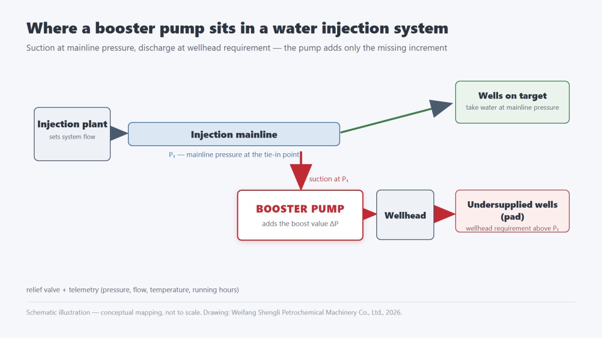
Booster injection means adding pumping capacity between the existing injection mainline and the wells that fall short, instead of increasing the pressure the plant delivers to everyone. The booster's suction is tied into the mainline — so the pump starts from mainline pressure, not from an atmospheric source tank — and its discharge is set by what the undersupplied wells actually need at the wellhead. The pump's job is to add the missing increment, what Chinese operators call the 增压值 (boost value), not the full head.
That is what distinguishes a booster from a new mainline injection pump. A mainline pump takes water near atmospheric pressure and must lift the entire injection pressure from the plant out. A booster inherits most of that head from the mainline and adds only the difference. The two machines answer different questions: one builds a system, the other repairs a pressure gap inside one.
The Binnan programme illustrates the demand side. The plant's approach combined classified treatment of under-injected wells, field-wide reallocation of produced water across reservoirs, and targeted pressurized injection at the low positions where remaining oil concentrates*1. Those are demand-side descriptions — they do not tell you which pumps were installed, and this article deliberately does not guess. What they do show is the shape of the requirement: local pressure increments, block by block.
Why a bigger injection pump is usually the wrong answer
Raising plant discharge pressure looks like the simpler fix, and it is the more expensive one. A mainline pump serves every well on the system. When its discharge pressure goes up, energy consumption goes up for all of them — including the wells that were already meeting their allocation.
Wells that were already at or near their injection pressure limit do not benefit from the higher pressure; they choke it back. That is pressure the operator paid to generate and then discarded across a choke. And injection pumps — particularly positive displacement machines — are selected against a duty point. Forcing a system-wide duty change does not simply add capacity; it shifts every pump in the chain off the point it was sized for, with predictable consequences for efficiency and for wear-part life in valves and packing.
For the pressure increment itself, the industry-standard machine is the reciprocating plunger pump: API 674 covers such pumps for petroleum, petrochemical and gas service*3, and ISO 13710 addresses the same class in its own scope*4. This is precisely why the booster exists as a distinct product category rather than a resize of the plant pump: high pressure, modest flow increments, duty that begins at mainline pressure.
The general principle, then: the gap is local, so the fix should be local. The rest of this article is about how to see that gap and how to specify for it.
Three signals that the pressure gap is local, not plant-wide
All three signals appear in the Binnan record: under-injected wells treated by class, targeted pressurized injection at remaining-oil low positions, and block-level campaigns such as the Li-71 area, where converted and boosted well groups brought noticeable response wells*1,*2. One detail from the same reporting shows why the effort pays: at Li-71X16, a well converted to injection at 200 cubic metres per day, the offset producer Li-71-5 saw its dynamic fluid level rise by 188 metres within four months*2. Pressure maintenance works when the water actually reaches the place that needs it — the booster is the tool that gets it there.
One caution belongs next to this table: these figures describe one operator's programme in one field. They are background, not a benchmark, and not a guarantee that any specific well will respond the same way. Injection response depends on geology as much as on surface equipment.
Where the booster sits — and what it must survive
In the simplest configuration, the booster taps into the injection mainline at or near the undersupplied pad, discharges to the wellhead, and carries its own protection and controls. Because the suction side is already pressurized by the mainline, the pump starts from a very different baseline than a plant pump drawing from an atmospheric tank. Booster designs for injection service — for example, the hydraulically balanced types used in Chinese mature-field programmes — are built around exactly this condition, with the suction pressure playing a structural role in how the power end and packing see the load.
What the booster pumps is often the harder half of the problem. Mature fields increasingly reinject treated produced water rather than fresh source water, and produced water brings suspended solids, high salinity, scaling ions and sometimes acid gas species with it. Those attack the plunger surfaces, packing, and valves first — the parts that already do the hardest work in a reciprocating pump. Where the water or the gas carries H₂S, material selection falls under NACE MR0175/ISO 15156*5. The exact tolerance of any pump model to solids load and salinity is a manufacturer question, and it deserves an answer in writing rather than an assumption.
Protection and control belong in the same breath as the pump itself. A booster raising wellhead pressure needs a relief path, pressure indication at suction and discharge, metering at pad level, and telemetry — pressure, flow, temperature, running hours — back to SCADA. On multi-pump pads, lead/lag alternation keeps wear even across the fleet. A booster that reports nothing is just unmanaged pressure.
One example of what this duty looks like in equipment terms: our own 3ZY100-series hydraulically balanced booster injection pumps are triplex machines with rated flow of 3.4–8.5 m³/h, boost values of 12–25 MPa, maximum discharge pressures of 27–45 MPa depending on model, pump speeds of 220–273 r/min, and motors from 30 to 55 kW.
Source: company technical datasheet, 3ZY100 series hydraulically balanced booster injection pumps. The table gives the range across the series; per-model selection depends on suction pressure at the tie-in point and the wellhead requirement, and is sized case by case.
What to fix in the specification before you buy
The specification is where booster projects succeed or quietly fail. Seven points belong in it:
1. Tie-in conditions. Mainline pressure range at the connection point — minimum and maximum, not a single design number. The booster's boost value is the discharge requirement minus this.
2. Wellhead requirement and boost value. State the increment the pump must add, separately from absolute discharge pressure.
3. Flow and fleet. Injection allocation per well now and after the campaign, and how many pumps: one duty, or duty plus standby, or a lead/lag pair.
4. Water. Solids, salinity, scaling tendency, acid gas content — and a request for material and seal recommendations written for that water, not generic ones.
5. Protection. Relief valve setting and route, suction and discharge pressure indication, and the treatment of any minimum-flow or deadhead condition.
6. Control and telemetry. Local panel or SCADA integration; which signals are transmitted; lead/lag rotation logic if more than one pump.
7. Package boundaries. Bare pump or skid-mounted package — scope, interfaces and room to grow are procurement questions in their own right; we treat them separately in our article on buying a skid-mounted injection pump package(内链 URL 待确认).
Weifang Shengli Petrochemical Machinery Co., Ltd. manufactures 3ZY-series hydraulically balanced booster injection pumps and 3ZB/5ZB-series water injection pumps, supplied both as bare pumps and as skid-mounted packages with control and remote-monitoring options defined together with the buyer.
FAQ
Why not just raise the plant discharge pressure instead?
Because the mainline serves every well. Higher plant pressure raises energy cost across the whole system, and wells already at their limit choke the extra pressure back. A booster localizes the increment: only the wells that need it pay for it.
Where does a booster pump connect in the water injection system?
Into the injection mainline, at or near the undersupplied wells. Its suction is already at mainline pressure; its discharge is the wellhead requirement. It adds the missing increment — the boost value — not the full head from atmospheric pressure.
What does produced water change for the pump?
Solids, salinity and acid gas species stress plungers, packing and valves first. Material selection for sour service follows NACE MR0175/ISO 15156, and the pump's tolerance to a specific water should be confirmed with the manufacturer in writing before purchase.
Superscript *n marks the numbered sources cited in the text.
*1 中国石化新闻网(Sinopec News). 巧做"水文章"激活上产新动能. 6 November 2026. www.sinopecnews.com.cn/xnews/content/2026-11/06/content_7160053.html
*2 大众新闻(Dazhong News). 胜利油田滨南采油厂增压提注报道(利 71 区块 33 个井组增压提注等数据). 2026 年 11 月.
*3 API. API Standard 674 — Reciprocating Positive Displacement Pumps for Petroleum, Petrochemical, and Natural Gas Industries. 3rd edition, 2010. www.api.org
*4 ISO. ISO 13710:2004 — Petroleum, petrochemical and natural gas industries — Reciprocating positive-displacement pumps. www.iso.org
*5 NACE/ISO. NACE MR0175/ISO 15156 — Petroleum and natural gas industries — Materials for use in H₂S-containing environments. www.iso.org