


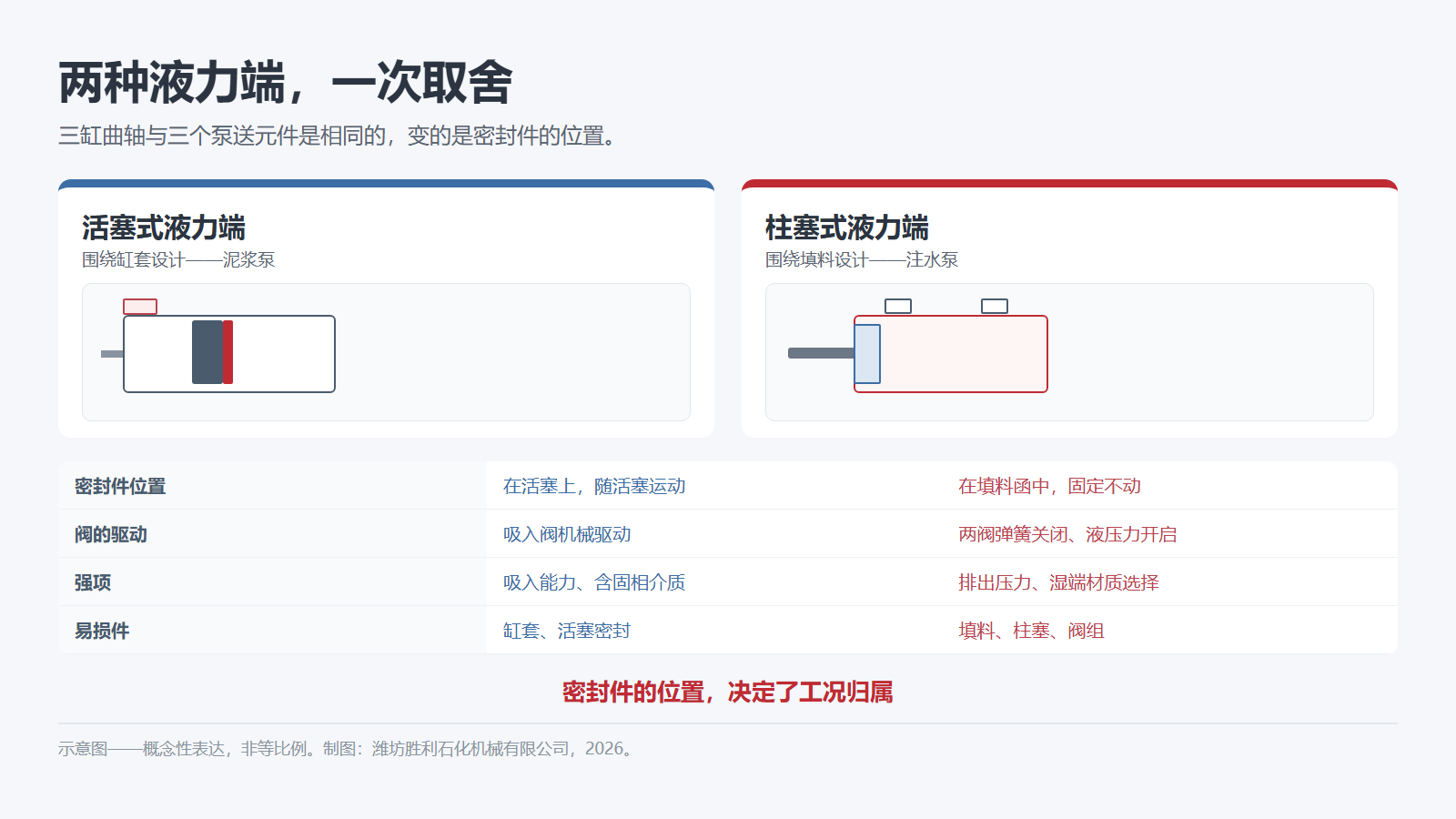
Same triplex crank, different fluid end: the seal position decides whether a pump is built for solids or for pressure.
Two fluid ends, one trade-off: suction against pressure
A mud pump and a water injection pump can look like cousins from the outside. Both are triplex positive-displacement reciprocating machines: three pumping elements, offset 120°, driven by one crankshaft, with flow set by displacement and speed rather than by pressure. Inside the fluid end, they are different machines — and the difference comes down to two decisions: how the valves are actuated, and where the seal sits.*1
In a piston design the seal rides on the piston, sweeping the liner bore on every stroke. In a plunger design the packing stays in the stuffing box and the plunger slides through it. That one change redistributes the entire trade-off. A moving seal tolerates a large flow area and fills the chamber efficiently — what a solids-laden drilling mud needs. A stationary packing confines the sealing area to a narrow annulus around a hard rod — what high pressure needs.
Valve actuation points the same way. Piston designs use a mechanically actuated suction valve, opened by the piston's own motion. Plunger designs close both valves by spring and open them hydraulically, so the flow path is simpler but depends on a pressure differential to work.
Neither arrangement is better in the abstract. One is built to swallow volume with solids in it; the other is built to hold pressure. Choosing between them is a duty question, not a preference.
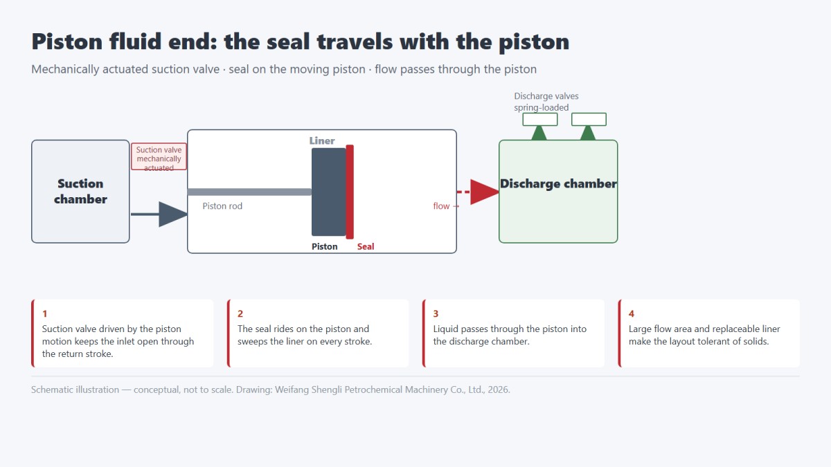
Piston fluid ends: how the seal rides with the piston
In a piston fluid end — one manufacturer calls the concept Uniflow — piston and seal move together inside a liner.*1 At the start of the stroke the mechanically actuated inlet valve closes; as the piston rod advances, liquid is forced out through the discharge valves while fresh liquid enters the inlet and collects behind the inlet valve. On the return stroke the inlet valve opens mechanically and the liquid continues forward through the piston into the discharge chamber.
Two properties follow from that layout. The first is suction capability: because the inlet path is driven mechanically and stays open through the return stroke, the pump fills reliably and the risk of cavitation is low — provided the pump is properly primed. The second is tolerance to solids: a large flow area, plus a seal that is designed to be replaced as a wear part, makes the layout practical for drilling mud and other abrasive slurries at the flow rates and moderate pressures a mud pump is specified for.
The costs are structural too. Liner and piston seal are consumables, and abrasive solids shorten the life of both. The pressure ceiling is lower than a plunger design's, because the sealing element is large and the liner has to be honed along its full length. The mechanical suction-valve linkage is one more item on the inspection list.
That is why the mud pump on a rig looks the way it does: large, slow-running, built around a liner, with a fluid end designed to pass solids rather than to contain extreme pressure.
Plunger fluid ends: how a fixed packing buys pressure
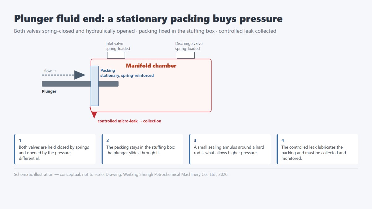
A plunger fluid end takes the seal off the moving part. The plunger — often a solid ceramic rod — reciprocates through a packing that is stationary, preloaded and spring-reinforced. Both inlet and discharge valves are spring-loaded closed and opened hydraulically, so the pump relies on pressure differential instead of a mechanical linkage.*1
Concentrating the seal in a small annulus around a hard rod is what allows significantly higher pressures than a piston design can reach. The sealing area is small, the rod surface can be finished and hardened, and the packing can be preloaded without fighting a liner. The same logic explains the material menu: manifold and valve bodies are commonly offered in brass, nickel aluminium bronze, stainless steel and duplex stainless steel, so the wetted end can be matched to water chemistry, CO2 duty or chemical compatibility.*1
The trade-off appears as leakage. A packed plunger is designed with a controlled micro-leak at the packing — enough to lubricate and cool the seal, small enough to be collected. That leak is not a defect; it is a design feature that needs a flush or collection arrangement. A rising leak rate is also one of the earliest condition signals a maintenance team receives. Abrasive solids are the other weak point: particles score the plunger surface, and a scored plunger consumes packing.
A third variant sits between the two. In a through-flow design — marketed as Superflow — the ceramic plunger is ported, so liquid enters through holes in the plunger itself.*1 Flow is continuous like a piston pump's while the sealing concept remains a packed plunger: strong suction at higher pressure, in the small-flow range.
Selection checklist: what to confirm before ordering
The structural question — piston or plunger — is settled by duty, not by preference. What follows is the list we want answered before a quotation is built.
Six steps keep the conversation in the right order:
1. Fix the duty point as a range, not a single number: flow, discharge pressure, and the lowest pressure the line will actually see.
2. Confirm suction: available NPSH, suction line length, priming method, and whether the fluid can flash.
3. Settle materials against the fluid, not against habit — water chemistry, CO2 phase, chemical compatibility, temperature.
4. Decide the leakage arrangement: collection, flushing, drainage, and who owns it inside the battery limit.
5. Choose the supply form, then write the interface down.
6. Agree the wear-part list and the service access before the order, not after the first failure.
The supply form deserves its own sentence, because it changes the interface rather than the price. A single injection pump suits a station where piping, controls and civil works are engineered by others and the pump has to fit an existing envelope. A skidded injection pump group — pump, driver, baseplate, manifolds, instrumentation and control on one frame — suits greenfield wellsites, remote pads and projects where commissioning time matters more than unit price. Which items fall inside the battery limit has to be written explicitly: suction and discharge flanges, electrical supply, control system and interlocks, lifting points, spares and training. The exact scope varies by project and is confirmed case by case.
Wear parts and service boundaries: lining up both designs
Consumables differ because the wear mechanism differs.
Two practical consequences follow. First, the spare-parts strategy is not interchangeable: a mud pump fleet stocks liners and piston seals, an injection pump fleet stocks packing, plungers and valve sets. Second, replacement intervals have to come from duty-specific service data — solids loading, pressure, running hours, water quality — and not from a generic table copied across applications. A number that is right for one field can be wrong by a factor of two in another.
For maintenance planning, the more useful discipline is condition-based: track flow at constant speed, discharge pressure, packing leak rate and valve behaviour, and let the trend set the interval. Both layouts give clear signals before failure, if someone is recording them.
Minimum discharge pressure: why valves need back-pressure
One constraint applies to all three designs and is easy to miss in system design. The discharge valves are spring-loaded, and the cited technical reference puts the minimum discharge pressure needed for them to open and close properly at 7 bar (100 psi).*1 Below that, valves do not seat reliably; running near zero pressure for long periods invites flutter, seat damage and early failure.
In practice this is a system question rather than a pump question. If the duty genuinely requires low pressure — flushing, transfer, commissioning — provide a back-pressure path, such as a restriction orifice or a bypass arrangement, rather than asking the pump to run outside its valve requirement. It also helps to remember where pressure comes from in the first place: a reciprocating pump displaces a fixed volume per stroke, and pressure is created by the restriction downstream, not by the pump itself.*1
And it is a specification question. When a datasheet quotes a pressure range that starts at zero, the useful follow-up is what happens at the bottom of that range.
FAQ
Q1. Can a piston pump be converted into a plunger pump?
A: The fluid end is a design decision, not a parts swap. The valves, their actuation, the sealing arrangement and the manifold all change together, so conversion means a different fluid end and an engineering review — not a field modification.
Q2. Is leakage at the packing normal?
A: A controlled micro-leak is inherent to a packed plunger: it lubricates and cools the packing. What matters is that the leak is collected and that the rate is monitored. A rising leak rate points to packing wear or a scored plunger.
Q3. What does a skidded injection pump group include?
A: Typically the pump, driver, baseplate, suction and discharge manifolds, instrumentation, control and protective devices on one frame. The exact battery limit varies by project, so it is confirmed case by case rather than assumed.
Q4. Why three plungers?
A: Three elements offset by 120° balance each other's delivery, which keeps residual pulsation low and running smooth. Flow still follows displacement and speed, not pressure.*1
Superscript *n marks the numbered sources cited in the text. Entries are given in their original language; numbering is identical across the Chinese, English and Russian versions.
*1 CAT PUMPS, High-pressure pumps – the basics (technical knowledge page, last updated 2026-11-13). https://catpumps.de/en/knowledge/high-pressure-pump-basics/
*2 API Standard 674, Positive Displacement Pumps—Reciprocating. Cited as the terminology and framework reference only;
Related Posts
Online Message